A 98-qubit trapped-ion quantum computer with all-to-all connectivity
Abstract
Quantum computers require both high-fidelity operations and large qubit numbers to surpass classical capabilities1. Trapped-ion platforms have demonstrated the highest gate fidelities of any modality2,3,4,5,6 but scaling to larger qubit numbers while preserving performance has remained a central challenge. We report on Quantinuum Helios, a 98-qubit trapped-ion quantum processor based on the quantum charge-coupled device (QCCD) architecture7. Helios features 137Ba+ hyperfine qubits8,9, all-to-all connectivity enabled by a rotatable ion storage ring connecting two quantum operation regions by a junction10,11, speed improvements from parallelized operations12 and a new software stack with real-time compilation of dynamic programs13. Averaged over all operational zones in the system, we achieve average infidelities of 2.5(1) × 10−5 for single-qubit (1Q) gates, 7.9(2) × 10−4 for two-qubit (2Q) gates and 3.3(5) × 10−4 for state preparation and measurement (SPAM), none of which are fundamentally limited and probably able to be improved. These component infidelities are predictive of system-level performance in both random Clifford circuits and random circuit sampling (RCS), the latter demonstrating that Helios operates well beyond the reach of classical simulation and establishes a new frontier of fidelity and complexity for quantum computers14.
Main
As several quantum processing units (QPUs) demonstrate key milestones on the path to utility, including experimental evidence of quantum supremacy14,15,16 and the feasibility of fault tolerance17,18, the focus of progress is shifting to making use of the unique advantages of each architecture to scale to much larger sizes without affecting performance. Like all modalities, the trapped-ion QPU based on the QCCD architecture7,19,20,21,22,23 has its unique set of challenges and advantages in scaling. For example, trapped ions can require complex optical systems for implementing quantum operations. However, mobile qubit architectures, such as QCCD and optical tweezers24,25, can distribute resources more efficiently than stationary qubit architectures26,27,28, because qubits flow through the QPU like bits in a classical processor, with separated memory structures, data buses and logic units, each optimized for their purpose12. Here we present Quantinuum Helios, a 98-qubit trapped-ion QCCD quantum processor with three key advances from earlier Quantinuum QPUs21,22. First, Helios uses barium ions as the qubits8, achieving 99.92% two-qubit gate fidelity with a more scalable laser architecture. Second, Helios uses a four-way ‘X’ junction10,11,29,30,31,32,33,34,35 to connect memory regions to quantum logic regions without increasing electrical control or device fabrication complexity. Third, Helios is orchestrated by a new classical control implementation capable of executing truly arbitrary quantum programs with all-to-all connectivity and complex control flow logic. The cumulative impact of these advances enable us to scale the system size, from six qubits in the first QCCD quantum computer demonstrated five years ago21 to now 98 qubits, while setting a new state-of-the-art performance across all metrics, confirmed here by system benchmarks, including RCS, and seen in associated applications run on Helios in materials science and cryptography36,37,38.
Hardware and software architecture
QPU architecture and ion trap design
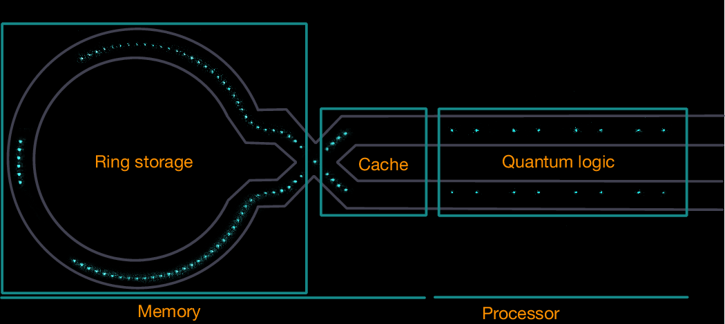
Helios is a transport-based quantum processor with spatially separated qubit memory regions and quantum logic regions. These elements are realized on a 2D surface electrode QCCD21,39, which confines ions with electric fields generated by a pattern of electrodes (Figs. 1 and 2), and the QPU uses individual ions for qubits. To apply gates to qubits or pairs of qubits, the ions are physically transported to isolated trapping zones to facilitate low-crosstalk addressing and maintain high fidelity.
An image of 98 atomic ions illuminated by resonant laser light in the Helios 2D surface trap illustrated in Fig. 2. The overlaid lines indicate different regions of the device, with the quincunx of ions showing the location of the ion trap junction.
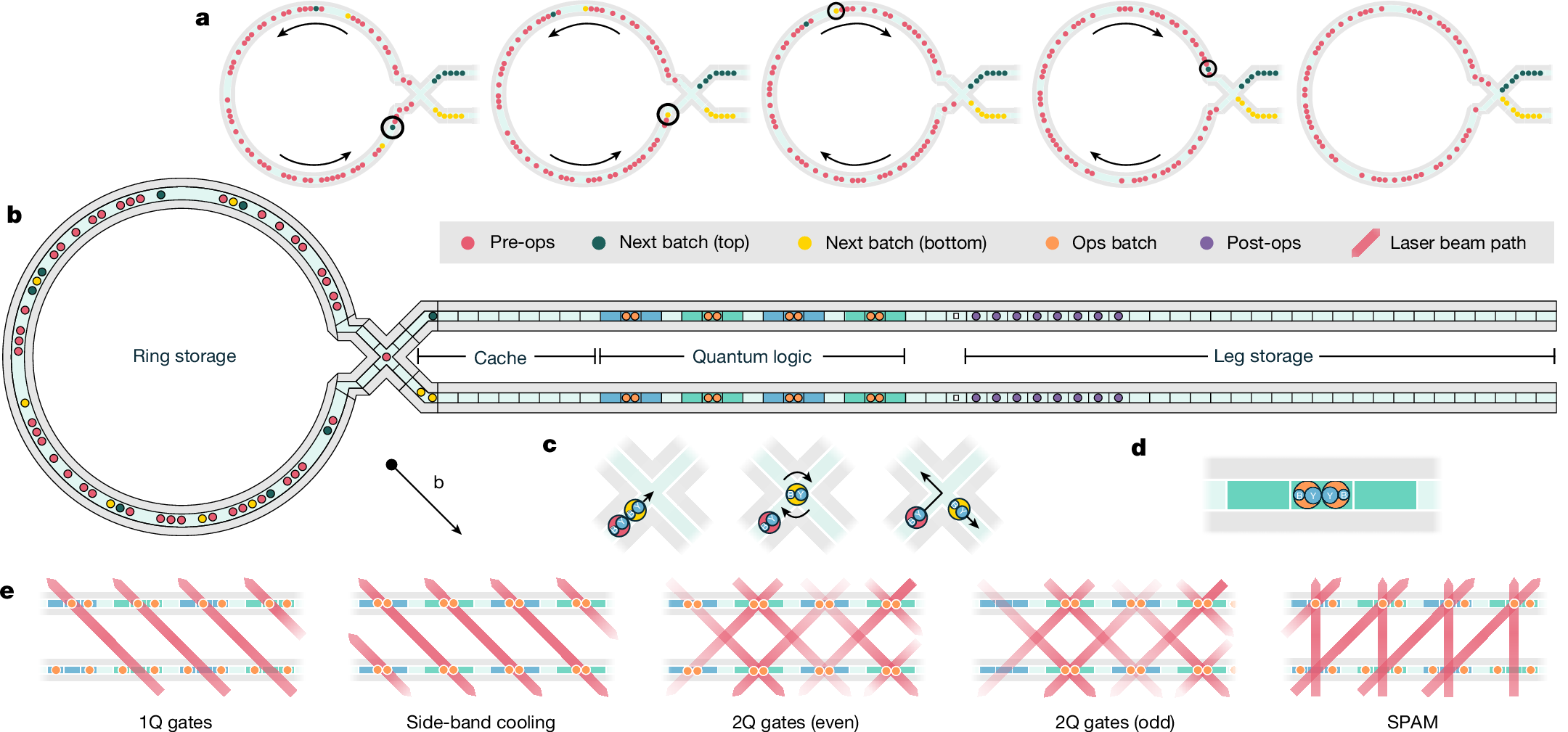
a, The final five stages of loading the cache region with qubits from ring storage. The ring rotates ions in both directions to move the circled qubit into the cache. b, Diagram of trap (not to scale) part way through a program. Ring storage qubits are being loaded into the cache and qubits in the quantum logic region are undergoing ground-state cooling. The actual horizontal length is 15.3 mm, the ring diameter is 2.8 mm and the operational zones are 750 μm apart. c, Junction operations shown with two ion pairs. The yellow pair moves into the junction, the ion order is rearranged and then it is transported out to the bottom leg. The red pair moves through the junction back to the ring. d, The proper alignment of a four-ion crystal in the quantum logic zones during 2Q gates. e, Laser beam and crystal configurations during example quantum operations as labelled. Beams are focused to operate on top/bottom legs as shown by colour gradients. The 2Q gate beams are tilted both vertically and horizontally away from the 45° line that intersects the ion crystals in both legs by approximately 1° so as to only interact with a single ion crystal at a time.
Figure 2 illustrates how Helios operates. The quantum logic region processes batches of up to 16 qubits at a time, using eight high-fidelity operation zones, each with the capability to perform state preparation, measurement, ground-state laser cooling and quantum logic gates. Each operation is implemented by means of focused laser beams propagating about 65 μm above and parallel to the chip surface, as shown in Fig. 2e. High-fidelity quantum logic operations necessitate low noise, independent electrode voltages and several laser beams for each zone, consuming most of the control resources in the processor. By using shared lasers across several operation zones (Fig. 2e), the quantum logic region design scales these essential components more efficiently than previous systems.
Qubits outside the operation zones are stored in functionally distinct memory regions: ring storage, leg storage and cache (Fig. 2b). Memory regions require fewer control resources as the only operations available are sympathetic laser cooling40 and qubit transport. To minimize the number of transport control signals, segmented DC electrodes in the memory regions use voltages that are broadcast in a repeating triplet pattern similar to in ref. 22. The cache is a small memory region that holds the next batch of pre-sorted qubits before going to the quantum logic region. The leg storage operates as a first in last out memory, whereas the ring storage acts as a random access memory, connecting to the operational region by means of an X-junction.
The junction is a key structure enabling this architecture. As qubits move through the junction, they can be routed to remain in memory or be added to the cache in either the upper or the lower legs. Furthermore, by implementing qubit routing in a separate structure from the quantum logic region, qubit sorting can proceed in parallel with the ground-state cooling of ions in the logic region, increasing the effective clock speed of the QPU. Comparisons with the Quantinuum H1 (ref. 21) and Quantinuum H2 (ref. 22) QPUs summarize the cumulative impact of these design choices in the electrical control subsystems (Table 1).
Ion species: qubit and coolant
Helios is the first programmable quantum computer we are aware of to use 137Ba+. We define |F = 1, mf = 0⟩ and |F = 2, mf = 0⟩ hyperfine levels in the 137Ba+ electronic ground state as |0⟩ and |1⟩, respectively. The optical transitions used to implement quantum operations are in the visible part of the wavelength spectrum, allowing for laser and optical components that are more mature, reliable and cost-effective and enables fundamentally better performance. Using more available laser power with better phase performance, we can suppress several of the leading sources of errors in logic gates, including spontaneous emission errors and laser phase fluctuations.
QCCD operation
In this section, we describe how Helios executes quantum programs using the operations depicted in Fig. 2. An arbitrary quantum program is decomposed into ion transport and quantum operations. These operations are not pre-planned but instead executed with a new real-time and dynamic classical control software called ‘Helios runtime’, which is described in detail in Methods.
Ions move through the trap using transport operations from four categories: shift, split/combine, junction transport and rotate. Shift operations translate ions along linear sections in the cache, quantum logic and leg storage regions. These operations can move both two-ion Ba–Yb (BY) and four-ion Ba–Yb–Yb–Ba (BYYB) crystals. Split (combine) operations separate (merge) BYYB (BY and YB) crystals in the eight operation zones. Junction exit (enter) operations move crystals from (into) the junction into (from) the desired leg in the cache with the desired order, BY or YB. Rotate operations collectively move crystals in the ring clockwise or anticlockwise.
Programs use these transport operations to move qubits between the memory and processor regions of the trap. This cycle occurs during a single layer in a program, in which qubits are removed from ring storage, processed in batches within the quantum logic region and then returned to ring storage. Every program begins with qubits in a default configuration: eight BYYB crystals in the quantum logic region and 82 BY crystals in ring storage. Each layer contains up to seven batches, with a maximum of 16 qubits per batch.
Using appropriate ion-to-qubit assignments, quantum operations immediately begin on the qubits already in the eight operation zones, with individual addressing operations occurring first: state preparation (or reset), 1Q gates and measure operations. Next, if 2Q gates are required, the BY and YB pairs associated with each zone are combined into BYYB crystals and ground-state cooling begins. In parallel with cooling, qubits for the next batch of gating are moved from ring storage to the cache. This parallel sorting with ground-state cooling allows cooling and gating cycles to run nearly continuously, as the next batch of qubits is ready to shift in as the current batch finishes operations.
Unlike 1Q, reset and measure operations, 2Q operations are executed in only four of the eight quantum logic zones (second and fourth zones on the top and bottom legs as shown in green in Fig. 2b,e). To perform 2Q gates on all 8-qubit pairs, the qubits are first merged and cooled as eight four-ion crystals in all operation zones and then 2Q beams are applied in the four 2Q operation zones. Immediately after executing the 2Q gates, the four-ion shift operation moves all crystals over by one zone (the crystals in the right edge operational zones are split into BY and YB pairs and then shifted into the storage legs). We then apply a small (approximately 300 μs) extra amount of cooling to remove any energy gained from the shift operation and then gate the remaining four crystals. The 2Q gate operation itself requires approximately 70 μs to execute.
After executing quantum operations, a batch is complete: its qubits move to leg storage, whereas qubits in the cache shift to the quantum logic region. This process repeats until all qubits requiring operations have been processed. Last, all qubits move from leg storage to the ring and the cycle begins for the next layer.
Figure 3a shows timing estimates and a breakdown of operations per layer for a representative program on Helios. The program is constructed as a sequence of ten layers, in which qubits are randomly paired and receive 1Q and 2Q gates each layer. We define the ‘depth-1 time’ as the time required to perform the random pairing and 1Q and 2Q gates in a single layer and use this time as our characteristic figure of merit for processor speed. We estimate the average depth-1 time by measuring the duration of the depth-10 program and dividing it by the number of layers to average any fortunate sort cases, resulting in an average of 55 ms per layer. To illustrate how program details such as 2Q gate density and qubit connectivity affect depth-1 time, we present timing results in Fig. 3b for three example programs as a function of the number of active qubits (Supplementary Information).
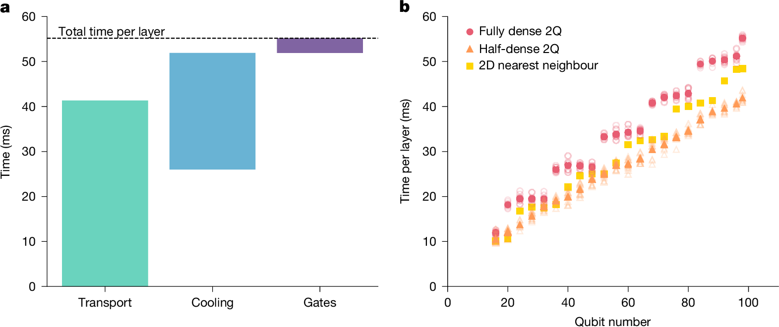
a, Time budget per layer for an example depth-10 random program that executes 1Q and 2Q gates on all 98 qubits after an arbitrary permutation each layer, broken down into three categories: ion transport, ground-state cooling and 1Q and 2Q gates. b, Total time per layer versus number of active qubits for three programs: a random program with fully dense 2Q gates, the same random program with approximately half the 2Q gate density and a program with 2D nearest-neighbour 2Q gate pairing. For the two random programs, solid points represent the mean of ten program instances and hollow points show the individual values.
Real-time compilation of sorting and gates
To realize the full capability of the Helios QPU, the system must be capable of executing arbitrary quantum programs efficiently, including dynamic quantum programs. Optimal decision-making for dynamic quantum programs requires a new classical control hardware unit and software compilation stack. This new stack both allows for real-time qubit routing decisions and increases the level of abstraction of quantum programs—mirroring the way classical computers advanced from writing assembly code to writing high-level programs.
In particular, Helios is the first trapped-ion QPU to translate operations on a program’s ‘virtual qubits’ (user program qubit variables whose physical qubit assignment depends on the structure of the program)41 into operations on corresponding physical qubits on the device in real time—that is, while the program is executing and quantum state is live. This is enabled by the Helios runtime, whose responsibility is to efficiently map virtual qubits to physical qubits on the device and turn declarative gates on virtual qubits into operations on physical qubits. This runtime enables state-of-the-art user programming constructs for use on a quantum computer (functions that can allocate and de-allocate qubits depending on the control flow of the program), early termination of programs based on mid-circuit measurement or arbitrary classical logic and classical control flow such as if-then-else statements, for loops and while loops. This is by strong contrast to the way most gate-level quantum programs, commonly referred to as ‘dynamic circuits’42, are written right now—as a flat series of gates with certain gates conditioned on measurements.
The core responsibilities of the Helios runtime are as follows: (1) receive qubit allocation requests on virtual qubits and resolve them to physical qubits; (2) receive gating requests on allocated virtual qubits; (3) transform requested gates on sets of virtual qubits into parallel operations on as many physical qubits as can fit in the quantum operation zones; and (4) transport batches of physical qubits from the ring into these zones, referred to as a ‘sort’. For details on how the Helios runtime performs these responsibilities, see Methods.
Benchmarking
To see how Helios performs in practice, we characterize individual operations with component-level benchmarks and measure full-device operations with system-level benchmarks22. Individual operations include SPAM, 1Q and 2Q gates and mid-circuit measurements and resets (MCMRs). We perform two separate system-level benchmarking experiments43,44,45,46,47,48, both of whic